Finalized 40-page manual for the UPLIFT Spaces Wall System (shown below)

The project
The UPLIFT Spaces Wall System is a complex, modular space system designed to provide customers with a variety of room configurations for their workspace. The instructions manual did not disappoint in being just as complex and has been by far the most enjoyable manual I have worked on at UPLIFT Desk. What made it so much fun is exactly its' complexity and the challenges that came with it. The end result is a 40-page manual that is well-organized, digestible, easy to follow, and beautiful.
Did I also mention my manager needed this project completed as soon as possible? Yes, that was also fun. Read below to see how I time-managed this complex manual to be completed in time for review and finalized while juggling other projects at the same time.

Table of Contents and Components page
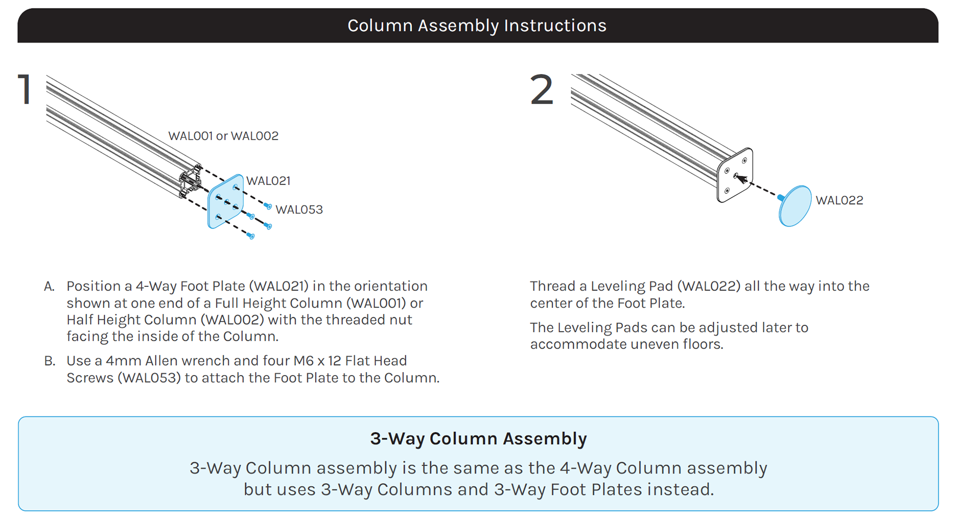
A quick glance at the design layout and formatting for each step in the instructions manual
The process
Step 1: Break down the information in a way that customers would feel confident about the assembly process and not intimidated.
First, I decided to break down the manual by separating each assembly process using three visual cues. The three visual cues are: colored backgrounds, prominent headlines, and visual representations of the actual products. These visual cues create recognizable breaking points throughout the manual allowing the customer to quickly locate their desired assembly step.
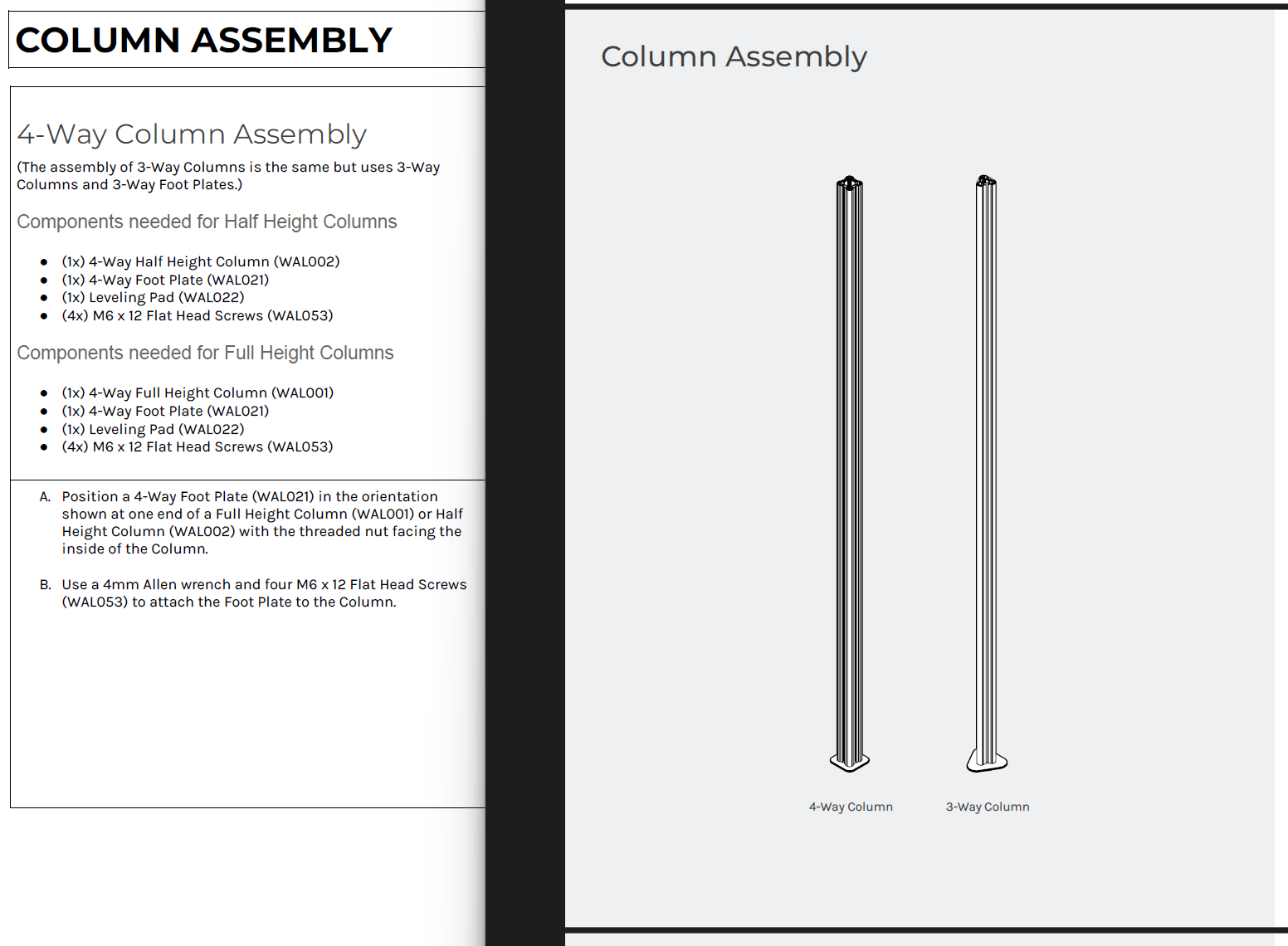
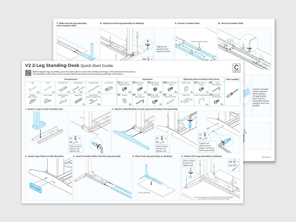
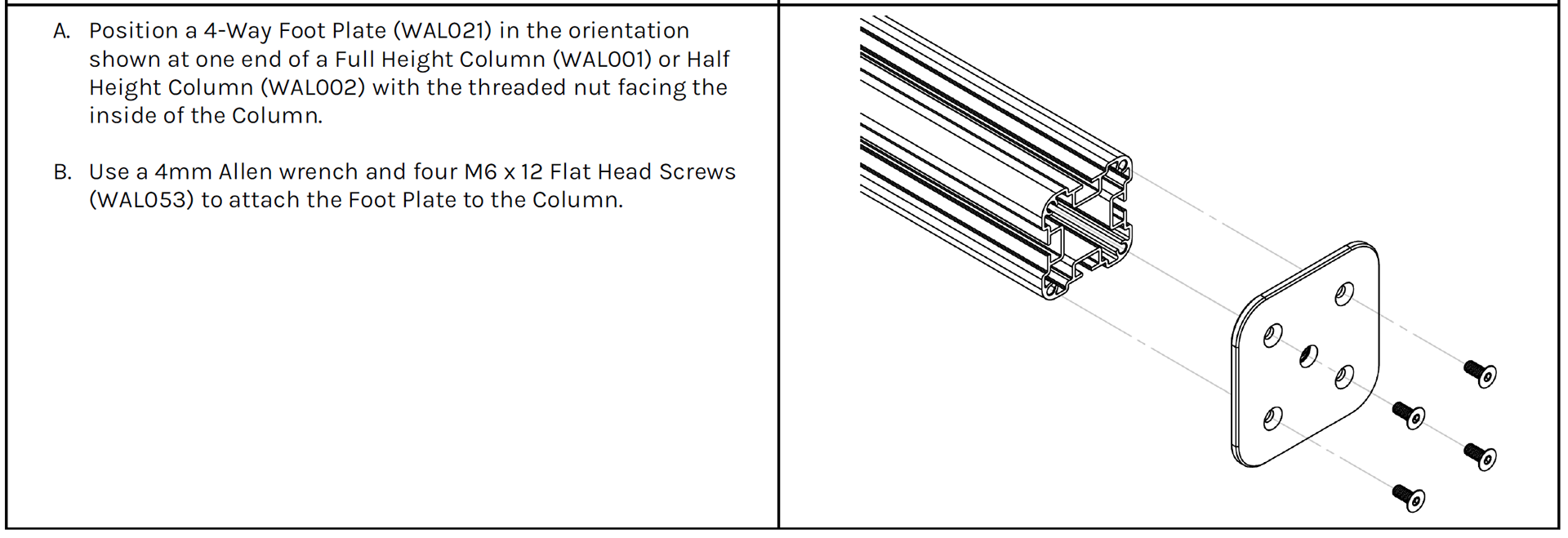
Shown left is the original copy with no visual representations. Shown right is an example of an assembly page being easily recognizable by visual cues.
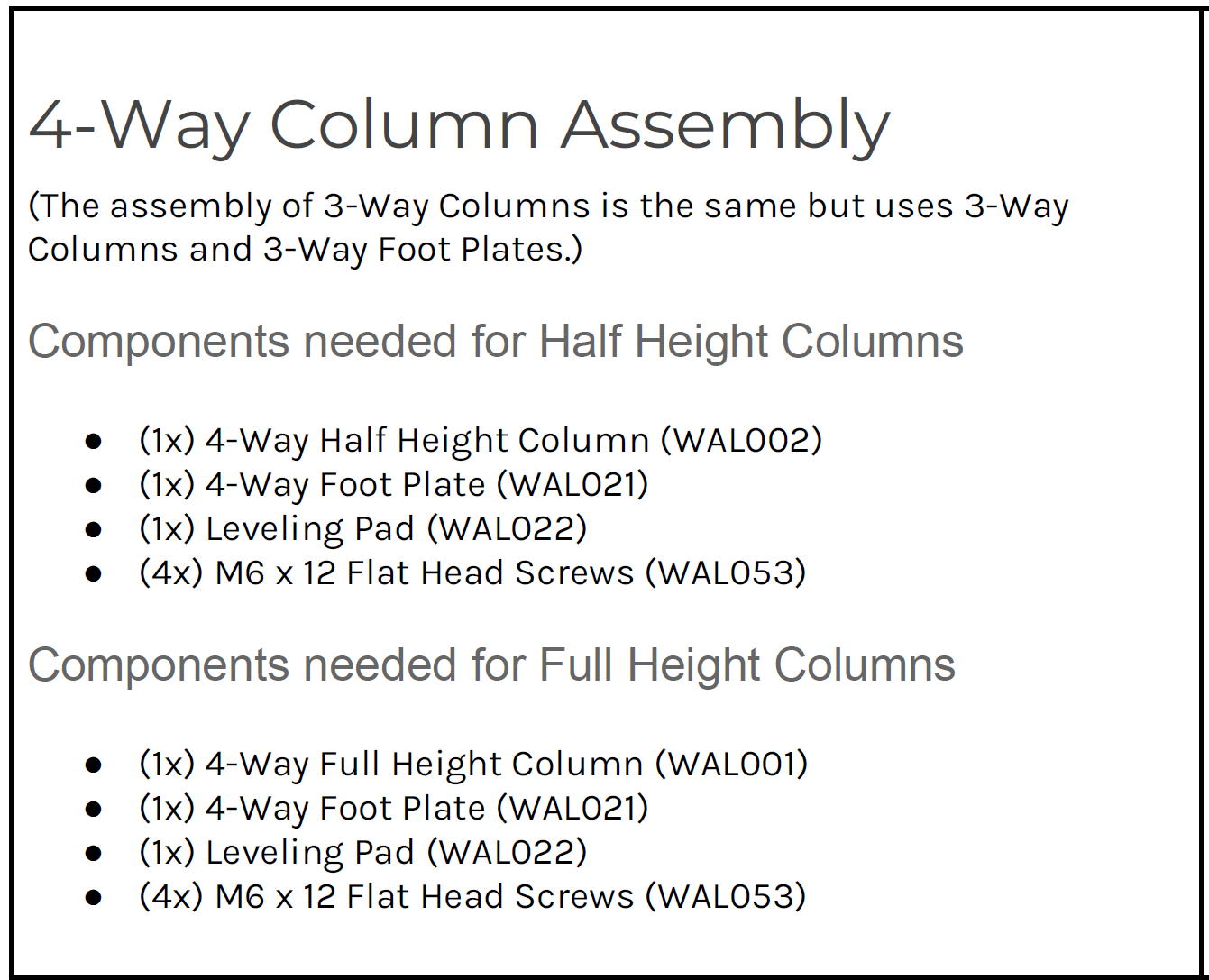
Step 2: Categorize assembly information by separating the components from the assembly steps using sub-headlines. Below is how I divided each sub-category.
Step 3: Re-imagine both the components and assembly sections for easier recognition and navigation.
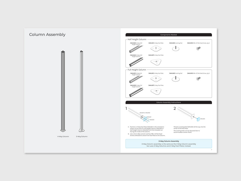
Components chart: One thing I like to do when organizing information is to create groups based on similarity and differences. Instead of having separate components charts, I decided to have a single components chart divided into sub-groups. This small change allows the customer to easily digest and navigate to their desired component list instead of having to find their components by reading lengthy sub-headlines. See below.
Original copy and format for the components section
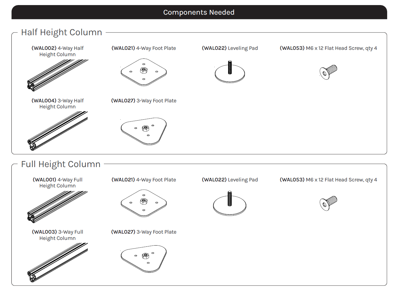
Components section re-organized and visually represented
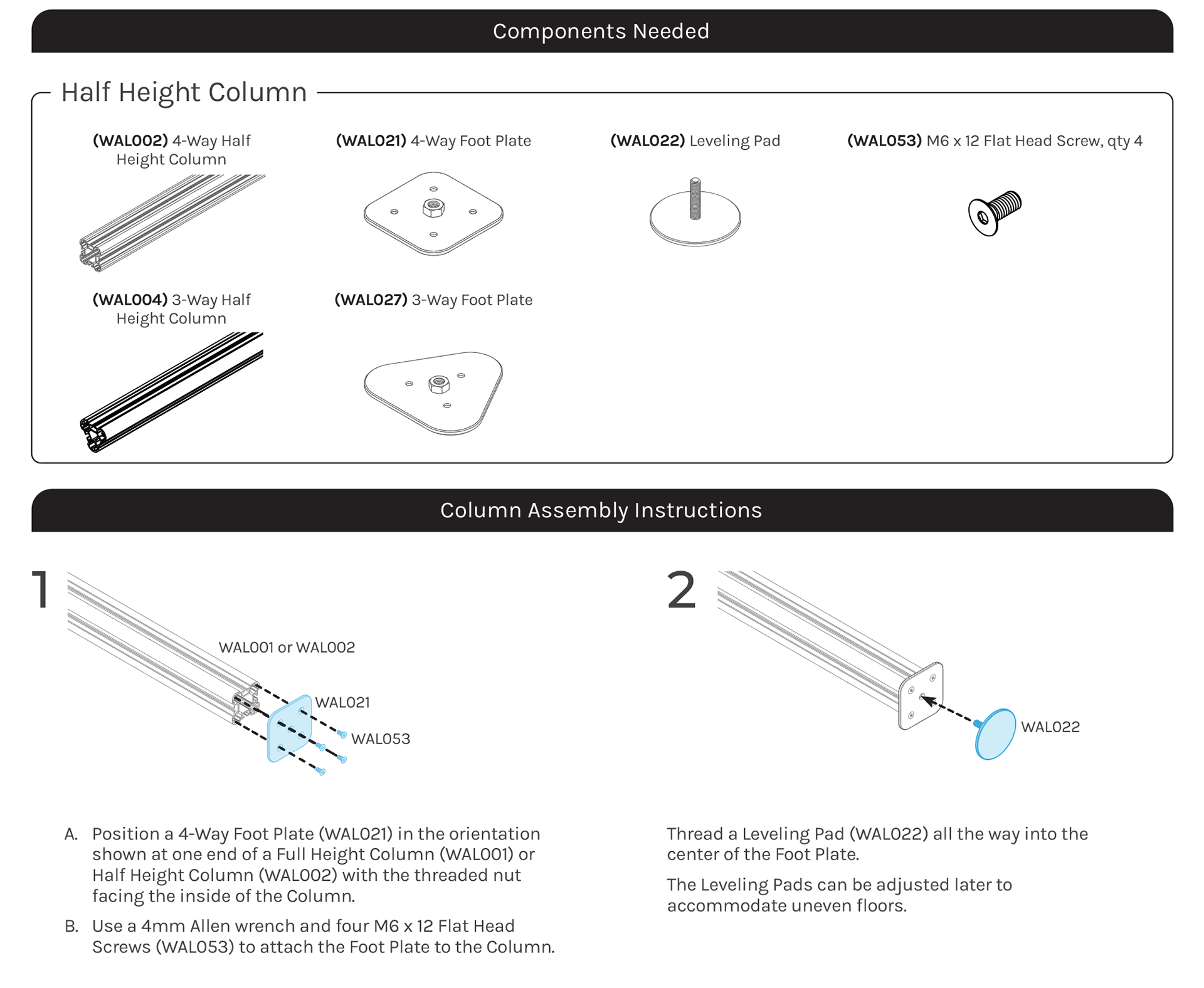
(Step 3 continued) Assembly steps: The assembly section was further broken down using a numbering system in order to ease the overwhelming amount of steps needed to build each assembly. It is also meant to help customers locate a specific step during the assembly process or when calling customer service.
Illustrations were provided by the engineering team and then cleaned up and finalized by me in Illustrator.
Step 4: Finalize the basic structure and layout of the first assembly page and have it approved by manager. Make improvements based on feedback and repeat the process for all other assembly pages.
Final product
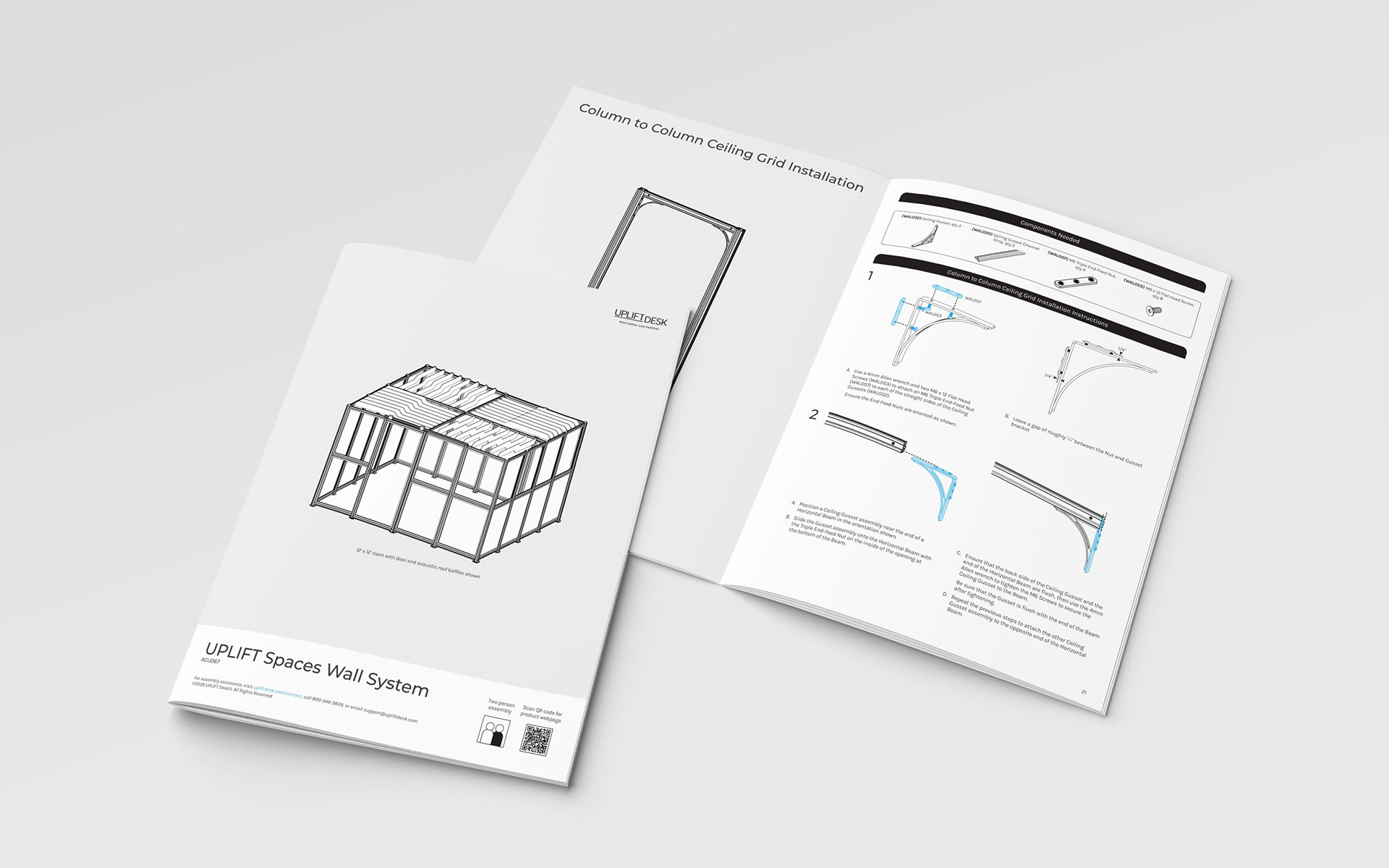
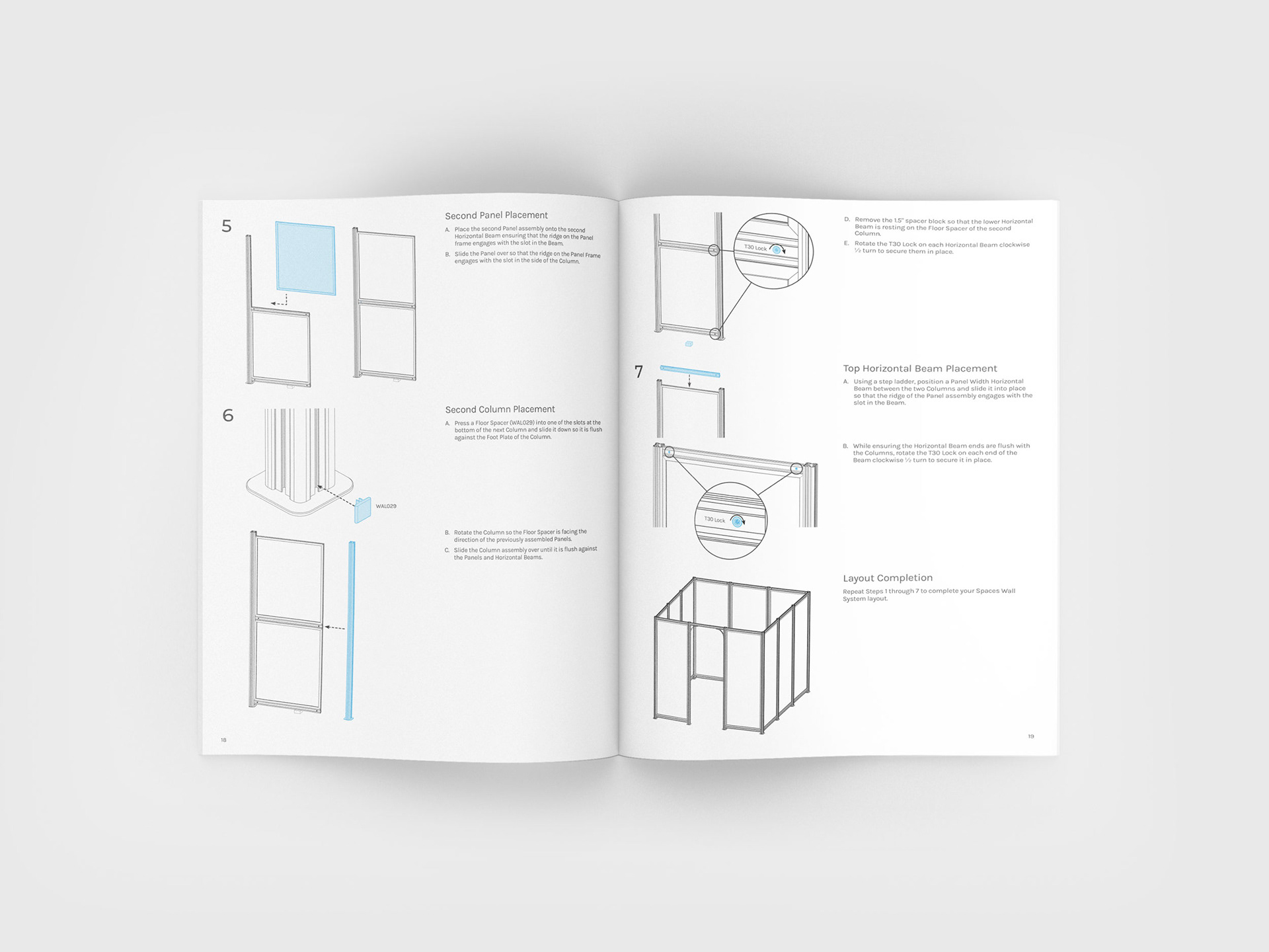
Below is a look at the final design layout, first four spreads are shown for reference.
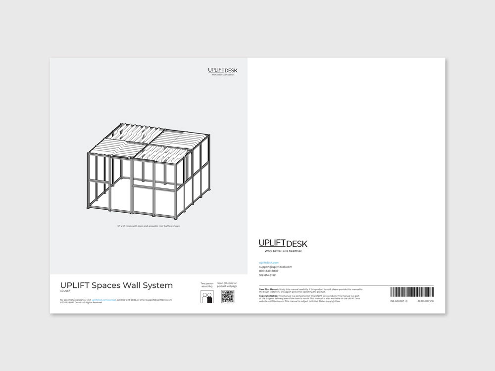
Front and back covers
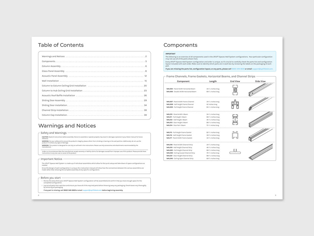
Table of Contents, Warnings and Components page
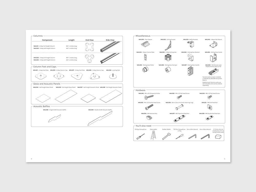
Components page (continued)